
Show me the POCUS
Airway Ultrasound
Introduction
Airway management is one of the most important and critical skills in the practice of Anesthesiology. Errors in this critical step of patient care is a major contributor to poor patient outcomes including brain hypoxia and death.
Not surprising, ultrasound has a role in this critical aspect of care that can assist in clinical decision making. Ultrasound can be used to evaluate vocal cord dysfunction and pathology before induction of anesthesia. It can be used to differentiate between tracheal and esophageal intubation as well as endobronchial intubation. It can be used to determine airway size and predict the approximate size of endotracheal tubes including double lumen tubes. It can also identify the cricothyroid membrane for emergency airway access plus distinguish tracheal rings for ultrasound guided tracheostomy.
Equipment and Technique:
The evaluation of the upper airway involves an evaluation of the floor of the mouth and the neck and its associated structures. The floor of the mouth can be examined with a curvilinear probe (1-8MHz). The neck and its associated structures are better visualized with a linear high frequency probe (13-6Mhz).
It is important to recognize the scanning planes of the different structures that will be introduced with the use of the following images.
Scanning planes
Transverse (or short axis) and long axis planes are defined according to the spatial relationship between the ultrasound probe and the structure of interest. In the following images we see the probe footprint position and its corresponding name.

Imaging planes used for airway ultrasound. On gray, long axis or longitudinal view of the floor of the mouth; red, short axis view of the floor of the mouth; green, long axis or longitudinal view of the neck and in blue, transverse or short axis view of the neck.
Anatomy of the Airway through a 3D model
We will be exploring ultrasound images with the use of this airway model to help us understand anatomic relations and orientation.


Anatomic model created and modified from Z-anatomy
Sonographic anatomy of the Airway, an Overview
Lets have a closer look at the corresponding images that we get with those scanning planes and later explore the clinical implications they have later in this chapter.

Anatomy of the larynx for reference purposes. Image By Olek Remesz
Floor of the mouth
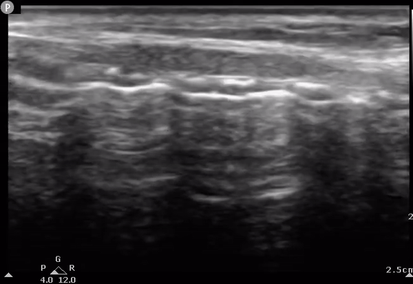
Ultrasound images of the floor of the mouth. In these images, the floor of the mouth is explored in long and short axis. On the long axis view we appreciate the acoustic shadow caused by the mentum (M) and hyoid bones (H) with the probe moved down the mouth and neck.

1
2

M
H
1

2
Floor of the mouth in long (label 1) and short axis (label 2) planes. Images obtained with a curvilinear probe and less than 5 cm of sector depth. The hyperechoic line deep in the image corresponds to the air-tissue interface of the tongue.
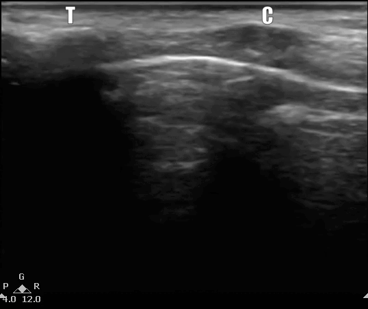
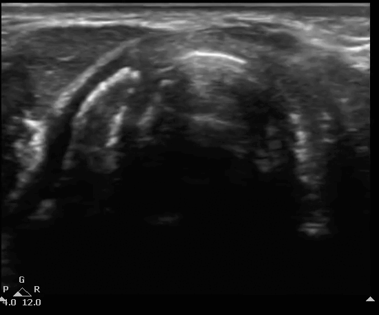
US of the neck
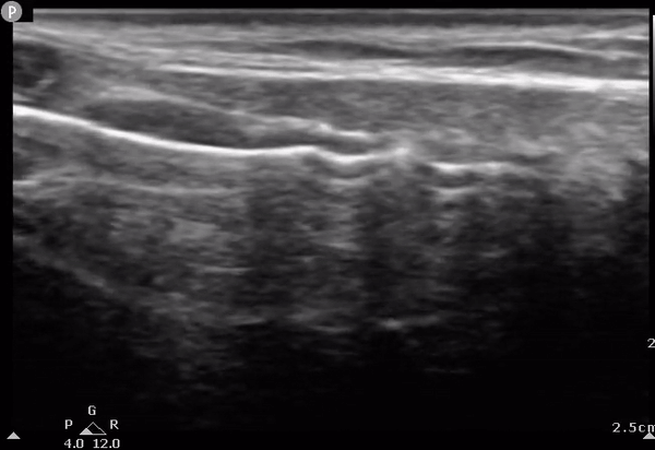
Here the floor of the mouth is explored in long and short axis. Bony structures create acoustic shadowing and thus limits the penetration of ultrasound waves into deeper tissues the hyperechoic line seen on these images corresponds to the air-tissue interface. We can use the following views to locate the cricothyroid membrane and the location of tracheal rings. If the esophagus lies directly posterior the trachea, is will not be visible on US.

1
2
1
Thy
2
US of the neck in both the long axis (label 1) and short axis planes (label 2). The probe is moving down from the head to the base of the neck. T, thyroid cartilage; C, cricoid; S, tracheal rings creating the 'string of pearls' configuration', Thy, thyroid gland appears deeper in the neck as the probe is moved down. Images here obtained using a linear probe with less than 4cm of sector depth.
Sonographic anatomy of the Airway on Short Axis
Lets have a closer look at what the different anatomical that you would see according to the interrogation planes along the short axis of the larynx. A diagram of the larynx and trachea is seen with slices taken at different levels as planes. Their corresponding ultrasound images are seen.

1. Vocal cords

5.Trachea

1
2
3
4
5
Anatomy of the larynx . Image By Olek Remesz

2. Thyroid cartilage

3. Cricothyroid membrane

4.Cricoid cartilage
Sonographic anatomy of the Airway on Sagittal Plane
Lets have a closer look at what the different anatomical that you would see according to the interrogation planes along the long axis of the larynx. A diagram of the larynx and trachea is seen with a single slice corresponding to the movement of the ultrasound moving from head to the base of neck.


Larynx viewed on long axis. The blue plane corresponds to the cut generated by the ultrasound beam. On the right we see the corresponding B mode clips while the ultrasound probe is moved in direction of the arrow above. Image By Olek Remesz
Anatomical structures and clinical implications.
Ultrasound of airway has various clinical implications that improve airway management which is what we will explore in this segment.
Cricothyroid Membrane
We often struggle to identify the cricothyroid membrane by visualization or external palpation which leads to a low success rate of cricothyrotomy so it is imperative that identification of this membrane happens before induction of anesthesia if possible. Ultrasound can help in this regard as it greatly improves its identification and the depth necessary to reach the airway. Lets identify this membrane on the planes described above.
String of Pearls Technique
Let's first look back at the anatomic model to visualize what bony structures we might be seeing. The clips below show a probe and sector moving up the neck in a sagittal plane towards the thyroid cartilage as the neck is extended.


This is the most well published and proven technique compared to palpation alone. This technique can also be used for optimal tracheostomy tube placement since it can accurately identify trachea rings.
Start by placing the probe at the base of the neck in a transverse orientation to get the short axis of the trachea in view which is visualized as a horseshoe shaped dark structure. Make sure that the midline of the probe corresponds to the midline of the trachea. Next, rotate the probe 90 degrees so that the indicator is pointing towards the head. A number of dark hypoechoic structures will appear corresponding to the anterior part of the tracheal rings that correspond to the 'pearls' of the String of Pearls technique. From here translate the probe upwards to the head. The cricoid is initially seen as a larger elongated hypoechoic 'pearl'. As the probe moves up the inferior portion of the thyroid cartilage is seen. The cricothyroid membrane can thus be located and can be marked.


String of Pearls technique. Probe movements and corresponding ultrasound images. A 3D model with a linear probe showing its projecting beam on the left. The probe is first placed transverse to identify the center of the trachea. The probe is then rotated 90 degrees and moved up for the String of Pearl technique. On the right, the corresponding US display. The string of pearls is seen before we can observe the cricoid and then the thyroid cartilage. The hyperechoic line that joins all the structures corresponds to the air-muscosa interface. See text above for more information. The label string on the clip corresponds to the last pearl of the string of pearls seen before the cricoid is seen. The 3D model was modified from Z-anatomy as are the rest of the models on this page.
Thyroid-Airline-Cricoid-Airline or TACA technique
Let's again first take a look at the 3D model to gain insight into the relevant structures and the orientation necessary to get this view. Here the probe and sector are seen moving down and then up in a transverse plane with an extended neck.


This technique is recommended when the SOP technique is not feasible due to limited neck mobility or very short neck. This technique can also be used in conjunction to the SOP technique for proper localization of the cricothyroid membrane.
Start at the level where you identified the thyroid cartilage and place the ultrasound probe over this structure. This cartilage appears a hyperechoic triangular structure. The transducer is then moved caudally with the cricothyroid membrane appearing as a hyperechoic white line. As the transducer is moved down further a C shaped structure corresponds to the cricoid. The transducer can then be moved back up the neck for marking of the cricothyroid membrane.


TACA technique. On the left the ultrasound probe movements on a 3D model of a trachea and relevant structures. The movements on this maneuver have been exaggerated for demonstration purposes. The probe is moved down once the thyroid cartilage is identified (Start on the US image) as a triangular structure. It is then moved down. The cricothyroid (CT) membrane is encountered next followed by the C shaped cricoid. The probe is then moved back up to the CT membrane. Start denotes the start of the clip. The labels appear for the duration of the clip they are seen on the looping video.
Lets have a closer look at the TACA technique based on still images to clarify the above concepts.
Below you will see an overlay of the bony structures on top of the ultrasound images as the movement of the probe slides down from the thyroid cartilage (position 1), to the cricothyroid membrane (position 2), then to cricoid (position 3) and finally back to position 2.
1. THYROID
3. CRICOID
2. AIR
2. AIR
B mode of the TACA protocol. Start at position 1 with the thyroid, followed by the cricothyroid membrane, then cricoid at position 3 and back to position 2 at the cricothyroid membrane.
Tracheal placement and location of endotracheal tube
Ultrasound of the airway can also be used to confirm proper positioning of the endotracheal tube as an adjunction to standards of practice (visualization between vocal cords, end-tidal CO2, and endoscopic visualization of tracheal rings through the endotracheal tube). Here the goal is to evaluate proper tube placement by indirectly ruling out an esophageal intubation.
Endotracheal tube not in the esophagus.
We start with the ultrasound probe placed in a transverse position at the base of the anterior neck. The tracheal rings will be identified as C-shaped hypoechoic structures with deeper hyperechoic structures corresponding to the tissue-air border. The esophagus will be seen on the side of the trachea as an oval structure with an hyperechoic wall and hypoechoic center. The probe can be placed while the placing the endotracheal tube. An esophageal intubation will create an adjacent hyperechoic structure posterolateral to the trachea, also known as the 'double tract sign'. Ultrasound may not be able to identify esophageal intubation in the case of an esophagus lying directly posterior to the trachea. The trachea in this case will cause acoustic shadowing of the esophagus and thus will not be seen. If the esophagus cannot be observed on initial evaluation moving the probe towards the left will help reduced the acoustic shadow caused by the thyroid cartilage.


E

E
Identification of the esophagus. To help identify the esophagus, movement of the probe to the side of the neck (either side) may be necessary as illustrated on the video to the left showing an US probe and its sector rotating towards the left and the corresponding image on the middle of the screen. E for esophagus. The right most image is taken on the side of the neck on the transverse view.
ETT in esophagus: Double barrel sign
Confirmation of the endotracheal tube (ETT) in the esophagus can be done with the double barrel sign. When interrogating the trachea with ultrasound there should only be one air-mucosa interface. The presence of a second air interface of a second air-mucosal interface implies that the ETT is actually in the esophagus.
E
E

DB
Intubation of the esophagus. Left: an empty esophagus that expands as an ETT is advanced and appears as a double barrel sign. On the right, the double barrel (DB) sign creating a second air-mucosa interface which implies the ETT is in the esophagus. The ETT has already been placed in this clip.
ETT in the trachea
The following are US signs can also be used to confirm the presence of the ETT in the trachea as well as its location within the trachea. These include the 'snowstorm' and the the 'bullet' sign. The snowstorm artifact is created when the endotracheal tube advances into the trachea. The bullet sign is a single air-mucosal interface with increased posterior shadowing and increased diameter of the trachea. The air in the ETT balloon causes displacement of the walls of the trachea creating this artifact.

Bullet sign as seen in B mode ultrasound. On the left, the ETT cuff is inflated after the tube has been placed. On the right, the same clip but with two features. A cross section of a hollow ETT with its cuff being inflated appears in the image. This is then followed by the 'bullet' image overlay. The displacement cause by the ETT cuff creates a wider bony surface and thus casting a greater acoustic shadow. Images taken at the suprasternal notch.
Location of the ETT in the trachea
We can use the long axis or longitudinal view of the trachea to determine the location of the endotracheal cuff to evaluate its proper position. The optimal location of an endotracheal tube tip is between 5 +/- 2cm from the carina on neutral position. The cuff should then lie below the cricoid and above the lowest suprasternal tracheal ring that can be visualized. Bear in mind that due to different size tubes and manufacturers it would be prudent to check for bilateral lung sliding to confirm both lungs are ventilating. On the following clips we can identify the crycoid, the tracheal rings and its relation to the endotracheal cuff.

CT
Inflated ETT cuff in long axis. Long axis view or longitudinal view of the trachea as the cuff is inflated. Both clips are display the same information. Right clip has an overlay of an ETT as the cuff is being inflating causing an anterior displacement of the bony structures of the trachea and in this case the cricoid is displaced and thus the proceduralist should advance the ETT. CT for cricothyroid membrane.
Tracheal US and ETT size
Optimal ETT Size
Ultrasound is a reliable tool to assess the infraglottic diameter of the upper airway. Ultrasound derived formulas to estimate the size of the endotracheal tube is superior to age and height-based formulas in estimating endotracheal tube size.
The correct size of tracheal tube was highly correlated with the subglottic diameter. This diameter is taken just below the cricoid cartilage. Linear models estimate endotracheal tube size with the following formula (keep in mind that while the internal diameter of a tube does not vary across manufacturers, the outer tube diameter does) :
When using US derived measurements to estimate the size of the ETT:
Neonate and infants:
ETT OD (mm) = 0.55 × SD on ultrasound (mm) + 1.16.
In children older than 12 months:
ETT OD (mm) = 0.01 × age (months) + 0.02 × height (cm) + 3.3.
Measurements of the airway at the level of the cricoid as its smallest diameter. Dotted line represents the measurements taken at the cricoid cartilage on its largest dimension representing the smallest diameter. T thyroid and C, cricoid.
Estimating the size of Double Lumen Tubes
Double lumen tubes (DLTs) are frequently to manage the airway in cases requiring one-lung ventilation or in critically ill patients but adequate sizing is often difficult. Inserting an inappropriate size can lead to significant clinical problems including unable to completely isolate the lung, severe injury to the airway, and the need to exchange the tube for a different size.
There are two main approaches for the correct selection of DLT size. First, there are reference tables based on height and gender. The second method incorporates radiographical information including tracheal width and and size of the left main-stem bronchus. Ultrasound (US) offers an alternative. There is a direct correlation between tracheal width and left main-stem bronchial width as measured by CT. Thus if left bronchial width cannot be measured directly, the tracheal width can be used to predict bronchial width. Tracheal width measured by US as a guide to determine DLT size does so in approximately 75% of patients which is comparable to that obtained by chest radiograph as a guide to estimate DLT. This measurement is the outer diameter of the trachea just above the sternoclavicular joint. The following table can be used as a guide to estimate left sided DLT size.

Guideline for determining proper left sided DLT (LDLT) based on tracheal width (TW) measured by US.
US of the trachea just above the suprasternal notch. Dimensions here reflect the transverse outer diameter (OD) of trachea or tracheal width.
LDLT size, left main bronchus diameter (LBM), and TW as measured by CT and TW by US. F, French. Modified from Sustic A and all.
An important relevant problem here lies on the fact that there are considerable dimensional differences among similarly sized DLTs from different manufacturers.
Percutaneous Tracheostomy
The trachea and paratracheal soft tissues of the neck can be readily examined with high frequency US probes of due to their superficial position. This implies that the anterior tracheal wall, thyroid and cricoid cartilages, tracheal rings, and pre-tracheal tissue may all be well visualized. Ultrasound can thus assist in tracheostomy placement in selecting the optimal intercartilaginous space for tracheostomy. US can predict the proper tracheostomy tube size for exchange in children by assessing the internal and external transverse tracheal diameter and the depth of the trachea.
C
T 1
T 2
T 3
AM
Determining the location of the tracheostomy site based on US findings. The US probe is moved on the long axis of the neck (longitudinally) until encountering the cricoid. The tracheal rings can then be numbered down from the cricoid down to determine optimal surgical location. C, cricoid; T1, first tracheal ring; T2, second tracheal ring; T3, third tracheal ring; AM, air-mucosal interface.
Vocal Cords
The vocal cords are best seen with an ultrasound transducer placed over the thyroid cartilage on a transverse or short axis view. They appear attached anteriorly to the internal surface of the thyroid cartilage and project posteriorly to the arytenoid cartilages. We can appreciate the movement of the vocal cords as triangular hypoechoic structures outlined medially by the hyperechoic vocal ligaments as oscillate and move towards the midline during phonation. Visualization of the true vocal cords is lower than that of the false vocal cords and worse in males above 18 years of age compared to females. True vocal cords can also be difficult to visualize owing to the calcification of the thyroid cartilage.
Laryngeal ultrasound can accurately screen patients and direct patients who have higher probability of vocal cord dysfunction.


Ultrasound of the true vocal cords. On the left, a linear probe and on the right, a curved linear probe were used to interrogate the vocal chords. The thyroid cartilage appears calcified which impairs the ability to accurately asses the vocal cords and we cannot appreciate vocal cord movement on phonation with the clip on the left. On the right we appreciate movement of the true vocal chords.
References
1. You-Ten, K.E., Siddiqui, N., Teoh, W.H. et al. Point-of-care ultrasound (POCUS) of the upper airway. Can J Anesth/J Can Anesth 65, 473–484 (2018). https://doi.org/10.1007/s12630-018-1064-8
2. Image of the larynx courtesy of By Olek Remesz (wiki-pl: Orem, commons: Orem) - Own work based on: Gray951.png, CC BY-SA 2.5, https://commons.wikimedia.org/w/index.php?curid=3492701
3. Kim EJ, Kim SY, Kim WO, Kim H, Kil HK. Ultrasound measurement of subglottic diameter and an empirical formula for proper endotracheal tube fitting in children. Acta Anaesthesiol Scand. 2013 Oct;57(9):1124-30. doi: 10.1111/aas.12167. Epub 2013 Aug 2. PMID: 23909603.
4. Sustić A, Miletić D, Protić A, Ivancić A, Cicvarić T. Can ultrasound be useful for predicting the size of a left double-lumen bronchial tube? Tracheal width as measured by ultrasonography versus computed tomography. J Clin Anesth. 2008 Jun;20(4):247-52. doi: 10.1016/j.jclinane.2007.11.002. PMID: 18617120.
5. Hegland N, Schnitzler S, Ellensohn J, Steurer MP, Weiss M, Dullenkopf A. Dimensional Variations of Left-Sided Double-Lumen Endobronchial Tubes. Anesthesiol Res Pract. 2019;2019:3634202. Published 2019 Sep 24. doi:10.1155/2019/3634202
6. Šustić, Alan MD, PhD Role of ultrasound in the airway management of critically ill patients, Critical Care Medicine: May 2007 - Volume 35 - Issue 5 - p S173-S177 doi: 10.1097/01.CCM.0000260628.88402.8A
7.Senussi, Mourad H. MD, MS1; Kantamneni, Phani C. MD2; Latifi, Mani MD3; Omranian, Ali P. MD4; Krveshi, Lirim DO3; Barakat, Amr F. MD1; Masri, Ahmad MD, MS5; Schmidhofer, Mark MS, MD1 Protocolized Tracheal and Thoracic Ultrasound for Confirmation of Endotracheal Intubation and Positioning: A Multicenter Observational Study, Critical Care Explorations: September 2020 - Volume 2 - Issue 9 - p e0225 doi: 10.1097/CCE.0000000000000225
8.Gottlieb M, Holladay D, Peksa GD. Ultrasonography for the Confirmation of Endotracheal Tube Intubation: A Systematic Review and Meta-Analysis. Ann Emerg Med. 2018 Dec;72(6):627-636. doi: 10.1016/j.annemergmed.2018.06.024. Epub 2018 Aug 14. PMID: 30119943.