US Guided Central line access
Central venous access is a fundamental clinical skill. It is a procedure that is commonly performed in the perioperative period. It is estimated that around 5 million central venous access catheters are placed annually in the US alone. Indications range from hemodynamic monitoring, administration of vasoactive agents, total parenteral nutrition, and for blood draws. In the management of shock, the Surviving Sepsis guidelines recommend measurement of mixed venous oxygen saturation which can only be measured with the use of central access catheters. Success of central venous access depends on patient anatomy, comorbidity and and skill.
Ultrasound use during central venous access is associated with fewer complications (bleeding, pneumothorax, nerve injury and airway compromise), fewer attempts and fewer failed procedures when compared to the landmark technique. Ultrasound is used to define a target vessel and surrounding structures and guide the needle tip through the vessel puncture process. It can also be used to confirm correct local placement of guidewires and catheters in the target vessel and thus detect guidewire and/or catheter malposition. Ultrasound-guided vascular access results in clinical benefits and reduces overall effective cost-effective. Adoption of ultrasound guidance may have significant favorable impact on the risk of catheter contamination and catheter related infection and on the risk of catheter related venous thrombosis. Here we will be reviewing the ultrasound images for optimal performance of central line placement.

Equipment
For cannulation we will be using transducers with a frequency between 5-15MHz and in most cases this implies linear probe. Bare in mind that a higher frequency probe will grant you better resolution (image detail) at the expense of not being able to penetrate deep into the tissue.
Preferably a small footprint should be chosen to fit well within a confined anatomical space.
2D imaging is the standard technology for ultrasound-guided vascular access. To improve cannulation, place the ultrasound screen within line of sight.

Central line placement steps summary.
The following is a series of steps to keep in mind when attempting to place a central line and then we will take a look at the steps where ultrasound is involved.
1. Check equipment. Before starting, the provider should have the necessary equipment before attempting central line placement. Most central line kits (see an example below) contain the necessary equipment for at least one individual including the catheter, dilator and wire, local anesthesia, syringes, and scalpel. It may also include suture and needle driver. You may need an ultrasound probe cover with sterile probe cover, since it is typically not included in the kit. Check your kit to see if you may need any additional equipment.
2. Evaluate for feasibility. Providers sometimes check the site of insertion before an attempt to evaluate for feasibility which includes the size of the vessel and presence of clot.
3. Prepare area and equipment. After full barrier precautions have been followed the surgical area is prepped with chlorhexidine (if not allergic) for 60 seconds. Flush the lumens of the central line and ensure the guidewire moves freely through the needle and catheter. The ultrasound probe is then placed on its cover following barrier precautions. Local anesthesia should be given at the level of the skin.
4. Use the Seldinger technique for placement of central lines. Providers here have 2 options here. To use the needle that contains a catheter (catheter-in-needle) or use the hollow steel needle. Regardless of the choice of type of needle the provider must advance a needle while performing negative aspiration on the plunger. US can be used here to evaluate needle position in real time (more on this later). The needle is advanced until there is return of blood to the syringe. The guidewire is then advanced through the steel needle. Alternatively the catheter is advanced and then the guidewire. Slightly withdraw the guidewire if arrhythmia is encountered. Once the guidewire is in its correct placement can be confirmed with the use of ultrasound (more on this later).
5. To place the central line now you must first create a nick in the skin at the entry point of the guidewire and the skin and then place the dilator. Once removed the central line can be advanced, secured and confirmed.
There are then 3 moments during the procedure when ultrasound aids you in the placement of a central line. An initial scan to evaluate the site, then for needle guidance and finally to confirm placement of the guidewire.

Central line kit. The image above is a central line kit from Arrow ErgoPack registered trademark

Ultrasound in Internal Jugular Venous Access
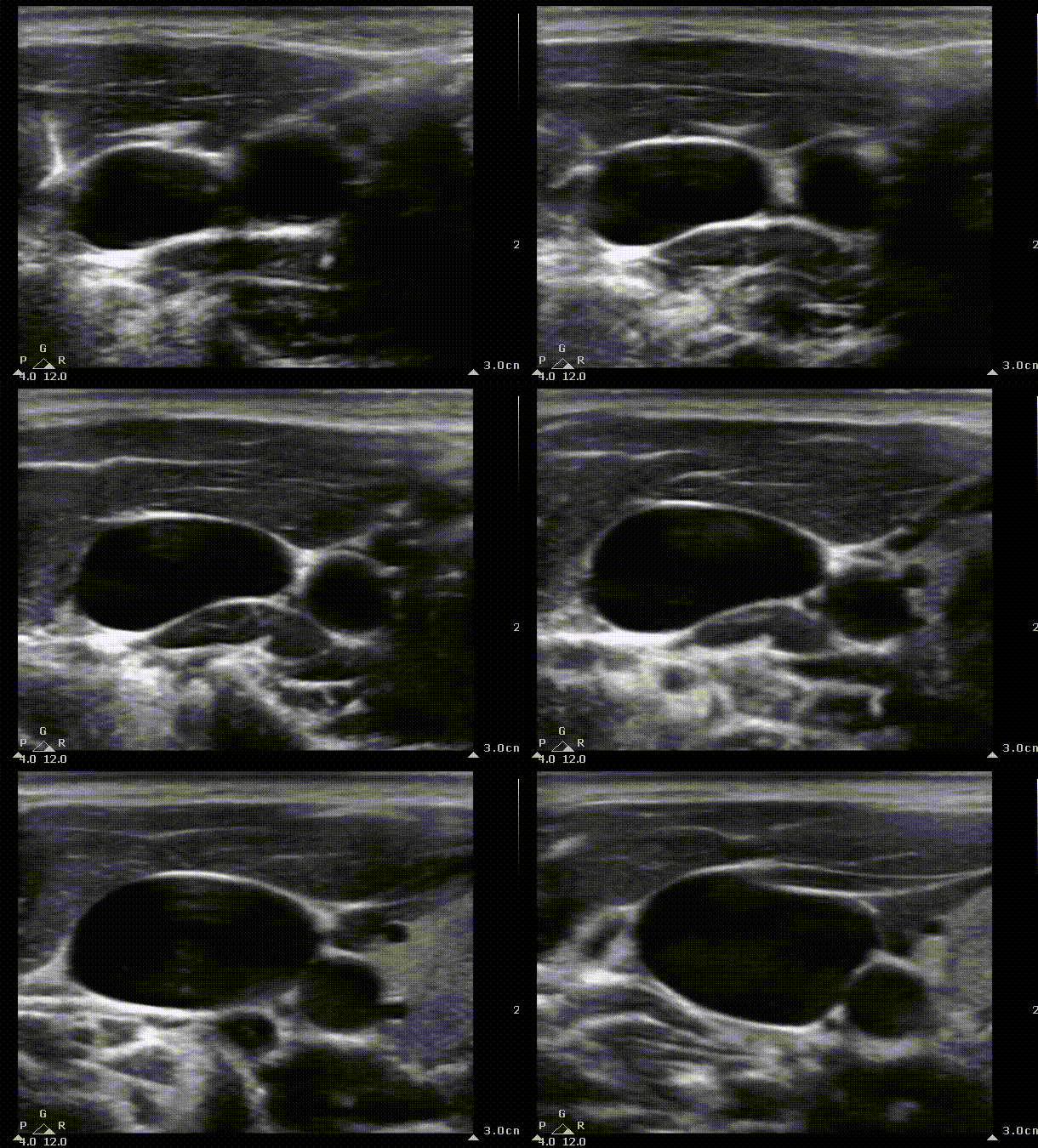
We can start by identifying the typical structures you should be seeing when scanning the internal jugular. You can create a mental picture of where the other structures are in relation to the vein. In this case the internal jugular appears to the right of the carotid.


SCM
IJ
Carotid
Short axis view of the internal jugular. Blue area represents the area that the ultrasound probe displays on the screen. The probe is slowly being moved caudally to create a mental picture of the structures that surround the vein. SCM, sternocleidomastoid muscule. IJ, Internal jugular. The arrow indicates the entry point of the needle in the landmark technique; in the apex of the triangle formed by the heads of the SCM and the clavicle.
Needle guidance
It is important to recognize the anatomical landmarks for internal jugular cannulation to understand the anatomic relations with the structures of interest. Ultrasound based methods are superior to landmark technique in terms of effectiveness and efficiency and safety profile. In the images below we see the Internal jugular vein pathway as it passes deep to the sternocleidomastoid (SCM) muscle. The entry point on the landmark technique is depicted by the syringe at an angle of 30 degrees on the apex of the triangle formed by the heads of the SCM muscle and the clavicle.


Internal Jugular (IJ) depicted in blue running deep to the SCM muscle. On the right the anatomic landmark technique for IJ cannulation. The syringe enters at an angle of 30 degrees at the apex of the triangle formed by the heads of the SCM and the clavicle.
Ultrasound for needle guidance can be used as dynamic or static technique. Dynamic or live mode implies that the needle is being visualized throughout the procedure with short and/or long axis views of the vessel. The static technique implies that it is only used for an initial mapping and then marked to proceed then without the use of ultrasound.
Once the location of interest has been selected the needle should be placed at an angle of 30 degrees at the skin and advanced with slight negative pressure on the plunger. Visualization of the tip is of paramount importance to minimize complications associated with the procedure. It is common for the provider to tilt the probe in the direction of the needle tip as it enters the skin when using the short axis view. You may not be able to get flashback of blood as the needle advances and only be able to do so when you start retracting the needle. This is due to a very pliable vessel.
The images below display a short axis and long axis view of the IJ while the needle is advanced (out of plane and in plane respectively).
It is much easier to do a short axis view while advancing the needle at the risk of not being able to identify the needle tip throughout the trajectory of the needle. A long axis view is more difficult to perform as the scanning plane has to be in line with the needle but provides better assessment of the needle tip depth as can be seen her.

Short and long axis view of the IJ as the needle passes on the anterior wall of the vessel. On the left, an out of plane technique. The needle has been placed and the provider tilts the probe towards the patients head to visualize more caudal structures. This allows the performer to evaluate the trajectory of the needle. On the right, a long axis view of the IJ and an in-plane technique as the needle enters the vessel. On these images there is no collapase as the needle enters the structure. The carotid can be seen pulsating and deeper than the IJ (right clip) .

Confirmation of guidewire position
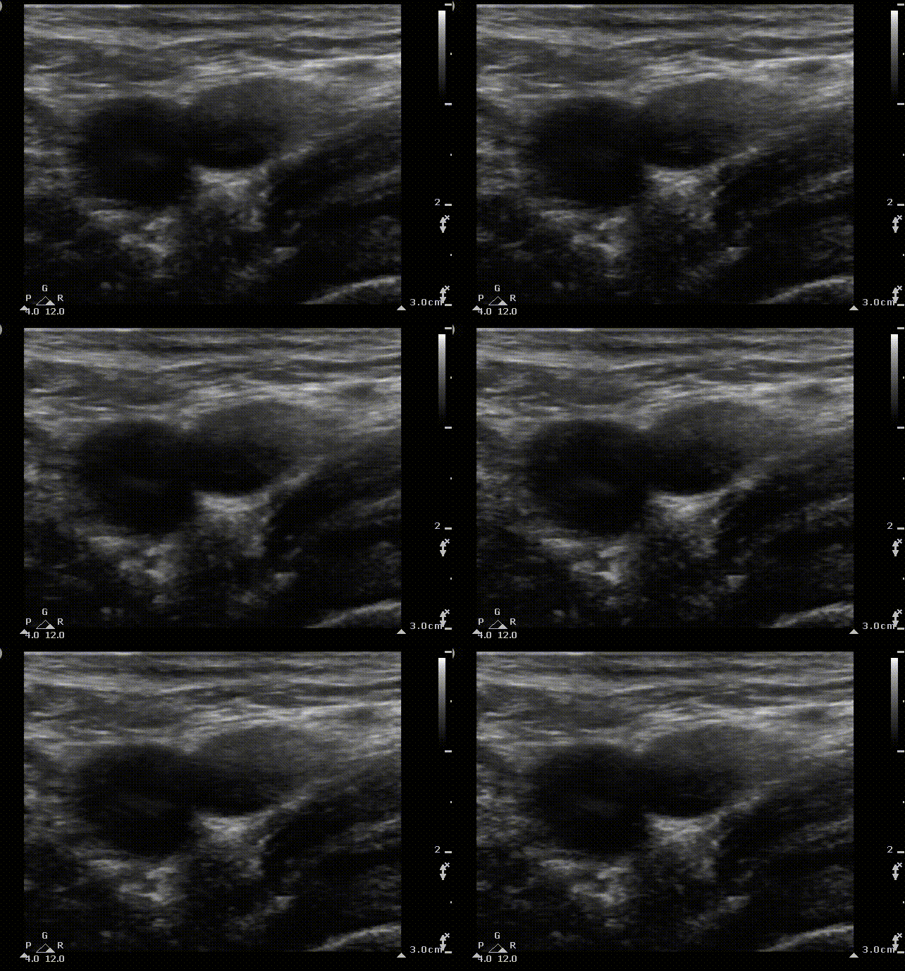
Once you have placed the guidewire following the Seldinger techique you may use ultrasound to confirm placement in the appropriate vessel. In the following images you see the guidewire both in short and long axis views. When using the short axis view it is important to follow the guidewire caudally by moving the probe down the patient's neck.
PSO

Misplacement of Central Line
The following images compare an adequate placed central line vs one that has been misplaced in the internal carotid. The marker on the right indicates the start of the central line as the ultrasound moves down the neck. Notice the acoustic shadow cast by the catheter This misplaced central line had no blood return on any of its ports.


Central line placement Subclavian/Axillary
Ultrasound can also be used safely and effectively for subclavian/axillary vein cannulation. Visualization of the subclavian vein from the clavicle to the brachiocephalic veins is possible. A longitudinal view allows for an in-plane approach. Supra and infraclavicular approaches have been described. Either method with an increased risk of pneumothorax particularly if out of plane method is used. In this segment we go more distally, at the level of the axillary vein and further away from the lung parenchyma. A recent observational study axillary vein cannulation had less complications compared to internal jugular cannulation.

1
2

Probe scan positions to visualize the subclavian/ axillary vein. On the left 1, long axis view of the subclavian vein as it passes deep to the clavicle.; 2, axillary vein in short axis. In plane approach is shown on these diagrams. On the right, the relevant anatomic landmarks for reference.

Axillary vein access
A closer look at the axillary vein and its anatomical relation is seen in this section


AA
AV
PMi
PMa
L
Axillary vein visualization on 2D ultrasound. On the left, the scanning plane cast by probe on the short axis view. You can appreciate pleura movement on this view. On the right, the 2D image. PMa, pectoralis mayor muscle; PMi, pectoralis minor muscle; AV, axillary vein; AA, axillary artery; L, lung.
Axillary Vein Technique
The axillary vein and artery are imaged on the short and then long axis views. The probe is then returned to the short axis view and an out of plane needle is advanced at a steep angle. The needle advances until the needle is seen to indent the anterior vein wall.

Short axis view of the axillary vein. Color Flow Doppler has been tuned on on the right image.

Central line placement in Femoral Vein


Femoral cannulation is a popular approach due to the relatively low incidence of life-threatening complications. Complications include an increased infection rate, accidental femoral cannulation and retroperitoneal hemorrhage and hematoma formation, especially in coagulopathic patients.
FA
FV
FN
Short axis view of the femoral vein. Blue area represents the area that the ultrasound probe displays on the screen. From medial to lateral we observe the femoral vein (FV), the femoral artery (FA) and the femoral nerve (FN)
References.
1. Lamperti M, Bodenham AR, Pittiruti M, Blaivas M, Augoustides JG, Elbarbary M, Pirotte T, Karakitsos D, Ledonne J, Doniger S, Scoppettuolo G, Feller-Kopman D, Schummer W, Biffi R, Desruennes E, Melniker LA, Verghese ST. International evidence-based recommendations on ultrasound-guided vascular access. Intensive Care Med. 2012 Jul;38(7):1105-17. doi: 10.1007/s00134-012-2597-x. Epub 2012 May 22. PMID: 22614241.
2. O’Leary R and all. Ultrasound-guided infraclavicular axillary vein cannulation: a useful alternative to the internal jugular vein
Br J Anaesth. 2012 Nov;109(5):762-8. doi: 10.1093/bja/aes262. Epub 2012 Aug 23.


